
Due to the thermal characteristics of batteries, thermal management has become a critical component in the electrochemical energy storage industry chain. Breaking down the value distribution within the industry chain, the cost of batteries in energy storage systems accounts for approximately 55%, PCS accounts for about 20%, BMS and EMS together make up about 11%, while thermal management constitutes about 2%-4%. Although the proportion of thermal management in terms of value is relatively low, it plays a crucial role in ensuring the continuous and safe operation of energy storage systems.
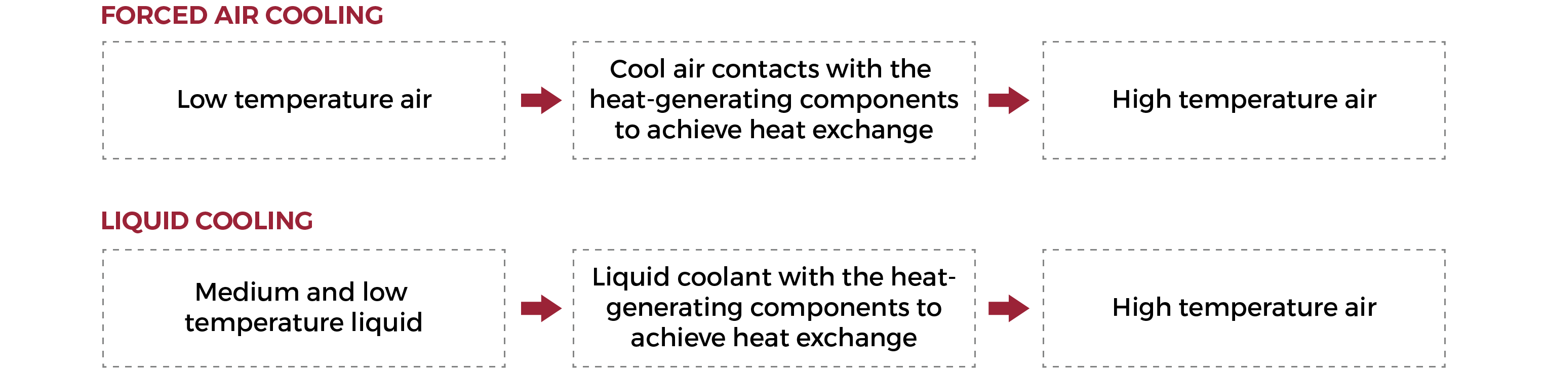
Currently, there are two mainstream solutions for thermal management technology in energy storage systems, namely forced air cooling system and liquid cooling system. This article will be divided into two parts to provide a comparative analysis of these two cooling systems in terms of lifespan, temperature control, energy consumption, design complexity, space utilization, noise, production & installation, after-sales, operation and maintenance, and cost.
Explanation of nouns
Thermal management technology: Including forced air cooling, liquid cooling, heat pipe cooling, and phase-change cooling, with the last two still in the experimental stage.
Forced air cooling: The main components of the air cooling system include air conditioning, air ducts, and module fans. The fans are installed at the front of the module. The module fans dissipate the heat generated by the module's internal cores and carry it out to the prefabricated cabin air duct. The air conditioning system inside the prefabricated cabin dissipates heat through convective heat transfer.
Liquid cooling: Liquid cooling system refers to the use of liquid as a heat-conducting medium, transferring heat directly or indirectly by coming into contact with cooling liquid and heat-generating components. It is a heat dissipation technique that removes the heat generated by the heat-generating components.
Chapter one: Life span comparison
Taking brand A 100Ah (P1, P2) and brand B 100Ah (P3) as examples, with 0.5C charge and discharge, the battery attenuation curve is shown below:
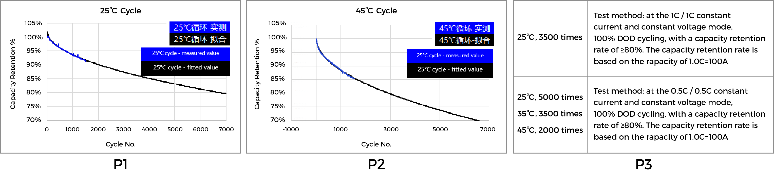
1. The attenuation curve from P1 to P2 shows that at 25°C, 6500 cycles at 80% EOL were achieved with brand-A cells, while at 45°C, 2500 cycles at 80% EOL were achieved with the same brand A cells. With a temperature increase of 20°C, the cycle life decreased by 4000 cycles.
2. P3 mainly reflects 5000 cycles at 80% EOL at 25°C (brand B cells) and 2000 cycles at 80% EOL at 45°C (brand Bcells). With a temperature increase of 20°C, the cycle life decreased by 3000 cycles.
3.Finally, from P4—comparing the service life of main components, it can be concluded that the service life of key components in the liquid cooling system is shorter. The operating temperature of the cells has a significant impact on their cycle life, and as the battery's operating temperature increases, the number of cycles decreases accordingly.
Chapter 2: Temperature control comparison
Summary:
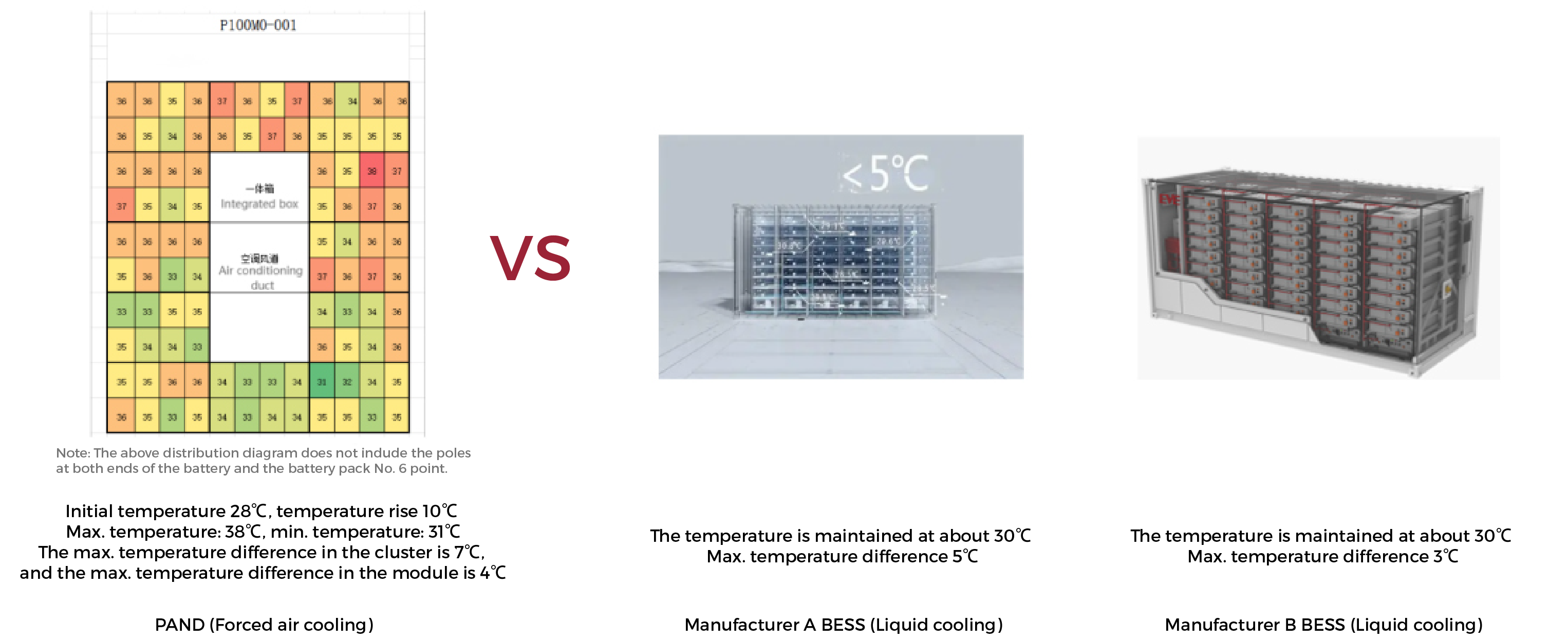
1. During the operation of the forced air cooling system (EnerArk2.0) , the temperature of the battery is approximately 31-38°C. For the liquid cooling system, referring to the Manufacturer A (30°C), Manufacturer B (30°C), the optimal operating temperature for normal batteries is 30-35°C. It can be seen that in terms of battery operating temperature, the forced air cooling has similar advantages to liquid cooling technology.
2. Liquid cooling system temperature differences: Manufacturer A (<5°C), Manufacturer B (<3°C). The temperature difference for the forced air cooling system (EnerArk <7°C). If there is a significant difference in the working temperature of the battery cells, the consistency of the battery cells will deteriorate. Air cooling can achieve a temperature difference of <4°C (EnerArk2.0 target value) by improving the air duct, then the effects of forced air cooling and liquid cooling on the battery would be the same.
Chapter 3: Energy consumption comparison
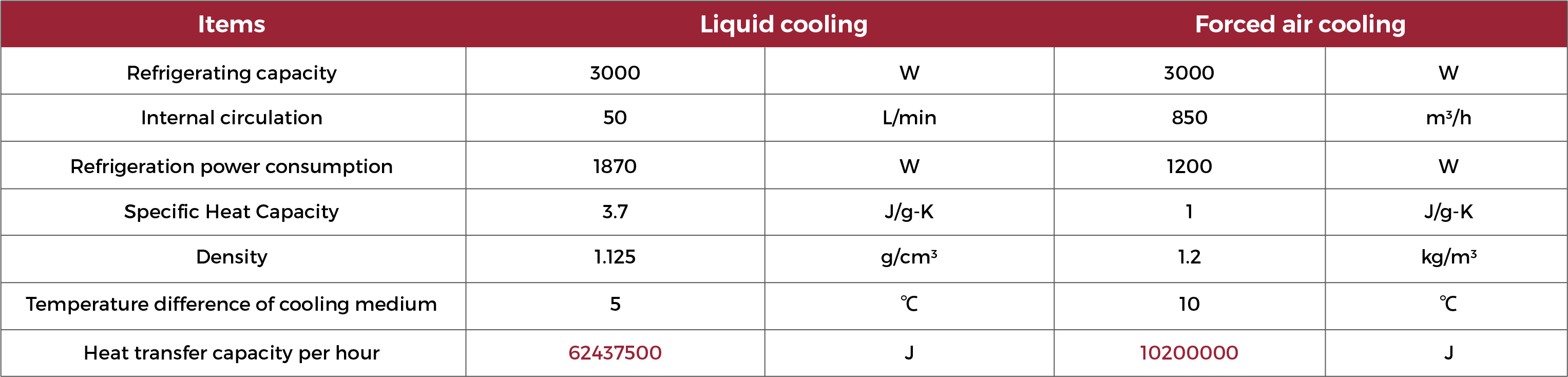
Take Envicool with the same cooling capacity of 3kW as an example:
Summary:
1. Comparing the heat exchange capacity, it can be seen that the liquid cooling system has 6 times the heat exchange capacity of the forced air cooling system. This can be understood as the air conditioning working at full cooling capacity for 6 hours, while the liquid cooling unit only needs to operate for 1 hour to achieve the same cooling effect.
2. Under the condition of equal battery temperature, for example, starting work at 20°C, after running under the same conditions for 2 hours, even if the system stops charging and discharging, the forced air cooling system still needs to continue working for refrigeration to ensure that the core temperature tends to the normal value. The time for the liquid cooling system to approach the normal value is 1/6 of that of the air cooling system.
3. Forced air cooling power consumption: air conditioning + electrical cabinet fan; Liquid cooling power consumption: liquid cooling unit + electrical cabinet fan (some manufacturers use integrated liquid cooling for the entire machine).
4. Under the same conditions, maintaining the same temperature, the power consumption of forced air cooling is higher than that of liquid cooling.
Chapter 4: Design complexity comparison
A: Forced air cooling system
Taking EnerArk2.0 as an example, the design of the air-cooled energy storage system is relatively simple, primarily involving the installation of cooling fans and the design of air circulation pathways.
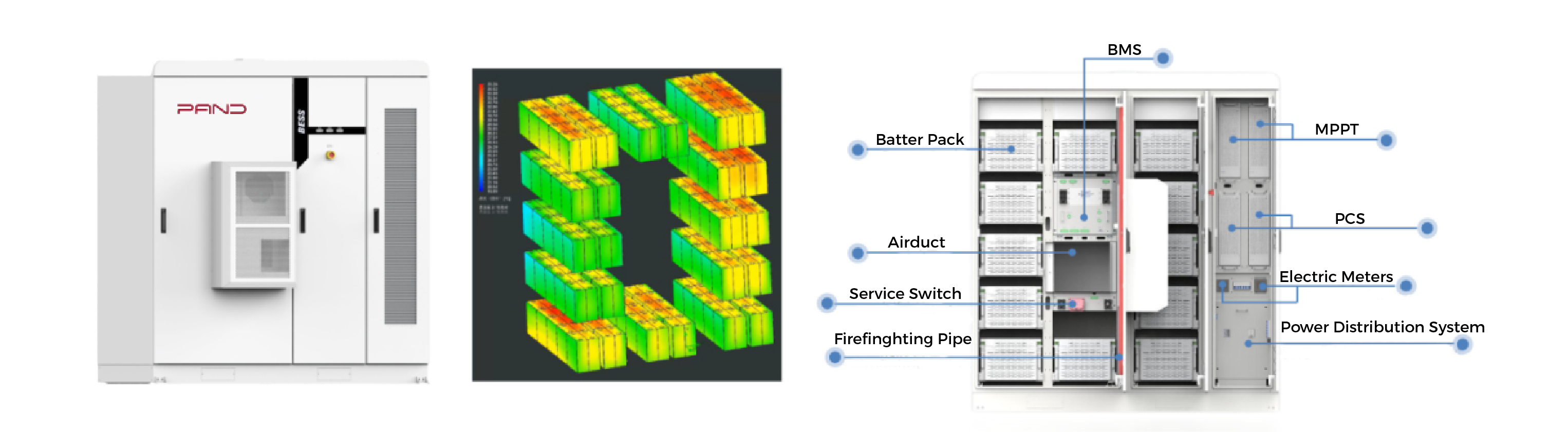
1. The core components of forced air cooling are air conditioning and air ducts. The air conditioning system is responsible for cooling, and the air ducts facilitate heat exchange.
2. In the application of energy storage projects, due to variations in battery energy density, positions, and capacity among different energy storage systems, it is necessary to customize the design of air ducts to control the airflow direction within the system.
B: Liquid cooling system
Liquid cooling design is typically more complex, requiring consideration of the layout of the liquid circulation system, pump selection, coolant circulation, and maintenance, among other issues.
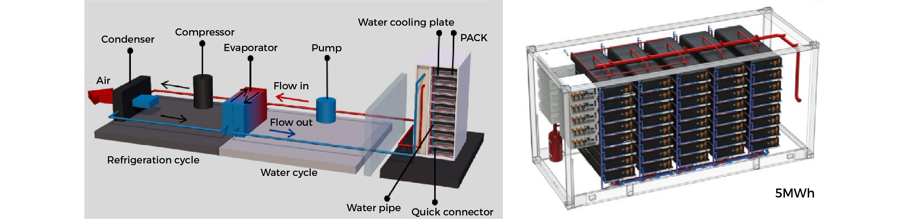
1. The liquid-cooled cooling plate (also known as a water-cooled heat dissipation plate) installed at the heat source, together with the heat exchanger and heat pump, dissipates heat through fluid circulation.
2. In general, the liquid cooling technology of the cooling unit in energy storage systems is applied when forced convection or phase-change systems cannot achieve effective heat dissipation, especially in environments with high thermal energy density.
C: Design complexity -- forced air cooling technology VS liquid cooling technology (The red font above indicates the design challenges.)
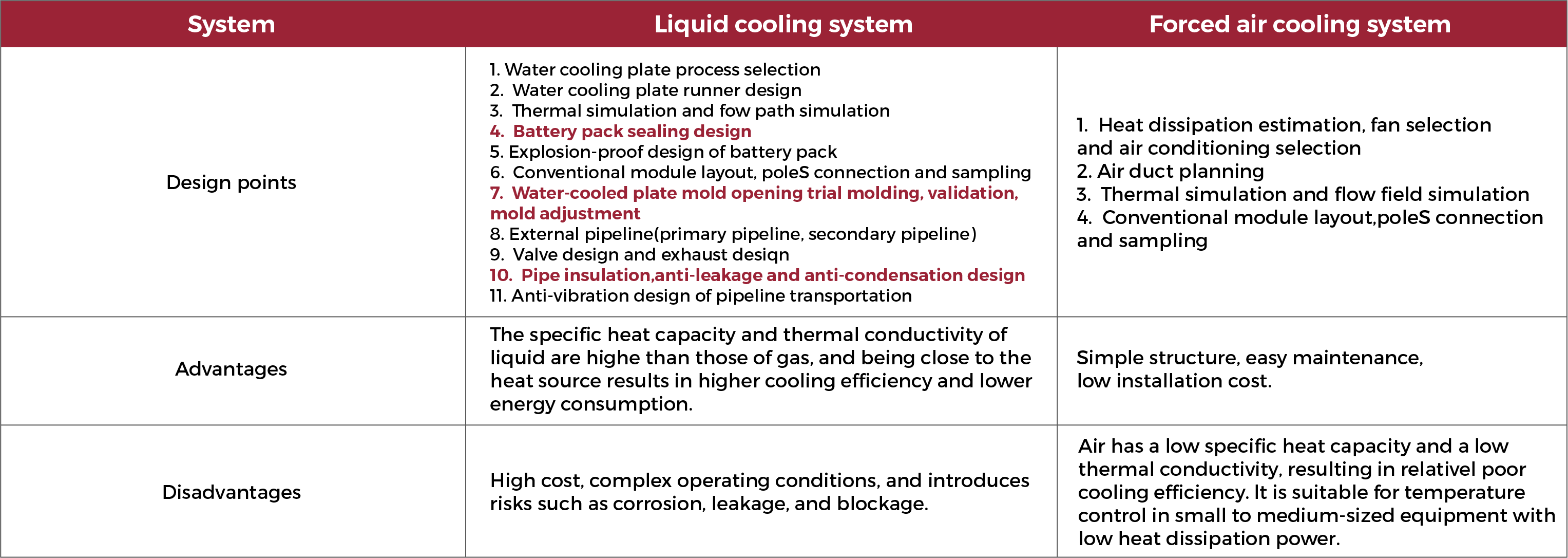
Conclusion:The design of liquid cooling system is more complicated than that of forced air cooling system.
Chapter 5: Spatial utilization efficiency comparison
Summary:
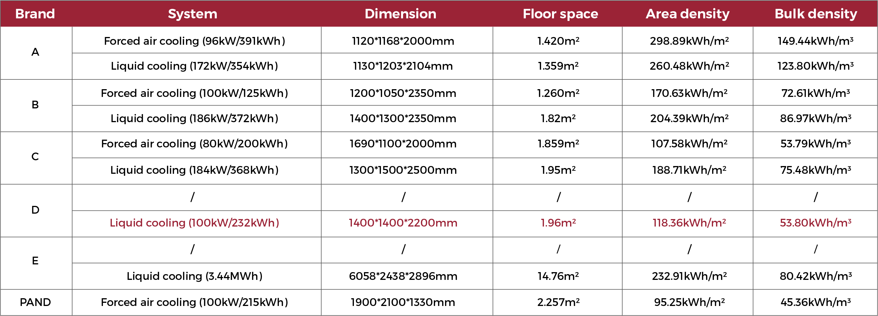
1. With the same footprint, liquid cooling system can achieve higher energy integration.
2. For the same energy integration (200kWh), forced air cooling systems outperform liquid cooling systems.

 2024-01-11